F-Zero
A few notes on F-Zero's operation. Teal represents RAM addresses and green represents headerless ROM addresses.
Contents
Track
Positions
Checkpoints
Palettes
Track tiles
Backgrounds
Physics
Track
The mode 7 background can only store 128x128 tiles / 1024x1024 pixels, which means that F-Zero unlike Mario Kart and a few others must update the surface as you progress through the track.
The game uses 2 buffers which hold 2 columns and 2 rows that are uploaded to an appropriate part of the mode 7 tilemap.
7F:4A00: Horizontal write buffer.
7F:4B00: Vertical write buffer.
During VBlank these buffers are copied. The horizontal buffer is written to a VRAM in a single DMA to an address on a 512 byte / 256 word page. The Vertical write uses 2 DMA transfers because of the non linear arrangement of 'columns' in VRAM. The VRAM word address is always between 00-80h so it always begins its write at the top of the tilemap.
7E:0094: This address holds the destination VRAM address written to $2116 for the horizontal writes.
7E:0096: Same as above, just for the vertical writes. It is incremented for the second DMA.
Some notes on how the track is stored. There are 3 tables which ultimately point a 2x2 tile pool.
Table 1: Fixed length of 512 bytes which determines track layout.
Table 2: Row pointer table, which is indexed depending on Y position.
Table 3: Row data, which is pointed to by Table 2 and indexed depending on X position.
Tile pool: 2x2 tiles selected according to what the row data specifies.
7F:4C00 - 7F:4DFF / 7F:4E00 - 7F:4FFF: Table 1; Track layout. 7F:4C00 - 7F:4DFF is contains almost identical data 7F:4E00 - 7F:4FFF, unless it is modified. The data in the 4E00 table data is copied into the 4C00 table, and then for some track sets it is modified. Tracks either index from 4C00 or 4E00, but it's only relevant if the track layout is modified. The panels are laid out in a 32x16 table.
When retrieving the required panel, table 1 is indexed by
YYYYXXXXX
where the X represents the highest 5 bits of the X coordinate, and the Y represents the highest 4 bits of the Y coordinate. X has a maximum range of 1FFF and Y 0FFF. This means bits 9-12 of Y and bits 9-13 of X are used.
This table is conditionally modified according to the values from a table in ROM.
66948: Base address of modification table. It's fixed in bank 0C from SNES perespective.
Bytes 1-2: Index
Bytes 3-4: Row 1 data
Bytes 5-6: Row 2 data
Each track has a pointer to this table. First, the Index is checked to see if the highest bit is set. The data in ROM shows FFFFh to either terminate after a series of loads, or as the first one pointed to which signifies no modifications are wanted. The modification process modifies 2x2 panels in table 1 (or 64x64 tiles) for every 16bit index loaded. Row 1 data overwrites 2 bytes at 7F:4C00 + Index. Row 2 data overwrites 2 bytes at 7F:4C20 + Index. It skips ahead 32 bytes / 1 row for the second write, yeilding a 2x2 panel change.
Here are the addresses which hold the pointer into the table for each track. The game only uses a byte for these so the highest base index you have is FF. Some tracks use the same pointer. Just add the byte value to 66948 to find the table address.
6693E: Big Blue
6693F: Silence
66940: Sand Ocean
66941: Port Town 1
66941: Port Town 2
66942: Death Wind 1
66942: Death Wind 2
66943: Red Canyon 1
66943: Red Canyon 2
66944: Fire Field
66945: Mute City 1
66945: Mute City 3
66946: White Land 1
66946: White Land 2
66947: Mute City 2
Big Blue, Silence, Sand Ocean, White Land 1 and 2 and Fire Field all point to an entry of FFFFh which causes no change in track layout. The rest have 1 track set as a base, and others which are built upon it. If a track has the same pointer as another, it means that one of the track layout tables is modified every time, but the layout table indexed differs. For example, Mute City 1 indexes the table ranging from 4C00-4DFF but Mute City 3 indexes from 4E00-4FFF. Again, 4E00-4FFF is first written and THEN copied to 4C00 where it is optionally modifed.
White Land + White Land 2 and Silence + Sand Ocean have identical track data and do not modify the first pointer table. Seeing as they have no resemblence, they don't use the same routine to modify track data. They store 2 tracks in the same table, but have different starting coordinates.
7F:5000 - 7F:6FFF: Table 2; Row pointer table. This table is indexed by the panel byte retrieved from table 1 x32, plus:
YYYY0
where Y represents bits 5-8 of the Y coordinate, and 0 is always 0.
The track is made out of 32x32 tile panels. Each one of these 2 byte entries points to a row of 32x2 tiles, implying that there are 16 entries here per panel. This table is effectively a row selector which works based upon the Y coordinate. A Y coordinate of 0 would retrieve the 1st 32x2 row, and one of 15 would retrieve the 16th 32x2 row. When the Y coordinate overflows during the vertical update, a new panel byte is loaded.
7F:7000 - 7F:FFFF: Table 3; Row data. This table is indexed by the 2 bytes retrieved from table 2, plus:
XXXX0
where X represents bits 5-8 of the X coordinate, and 0 is always 0.
There's 16 2byte entries in every row. Each of these entries represents 2x2 tiles. They point to the last table explained below. Note that rows are shared due to this layout alot. When the X coordinate overflows during the horizontal update, a new panel byte is loaded.
7F:0000 - 7F:24FF: Tile pool. This area is indexed by the 2 byte value of Table 3. This location is where all the VRAM ready tilemap bytes are stored. Because of the size of the tracks, the game uses collections of tiles as 1 element of a track. You could say it uses 'tiles of tiles'. For example, if you modify the data that makes up the pavement of lighter colour, you'd see the following universal effect. They're universal in that they're shared across the entire game.
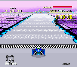
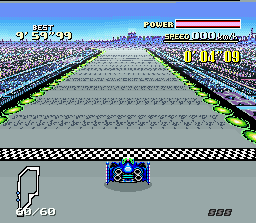
The tilemap bytes here are stored in a 2x2 per entry format.
Byte 1: Top left
Byte 2: Bottom left
Byte 3: Top right
Byte 4: Bottom right
The tilemap buffers explained above hold 128x2 for horizontal and 2x128 for vertical. The game fills the buffers with the appropriate 2x2 tiles 64 times to fill them entriely.
64380 - 6E87F: Shared by all tracks.
Locations in ROM for tables 1-3. The commas seperate table 1, 2, 3. The game automatically handles bank transitions. Shared means the game does not modify table 1; it uses exactly identical track data with modified starting positions.
19F80 - 1A17F, 1A180 - 1AE1F, 1AE20 - 1E4BF: Big Blue.
1E4E0 - 1E6DF, 1E6E0 - 1F9FF, 1FA00 - 255FF: Shared with Sand Ocean and Silence.
25600 - 257FF, 25800 - 2641F, 26420 - 2967F: Port Town.
29680 - 2987F, 29880 - 29E7F, 29E80 - 2BF8F: Death Wind.
2BF90 - 2C18F, 2C190 - 2D46F, 2D470 - 3039F: Red Canyon.
303A0 - 3059F, 305A0 - 3139F, 313A0 - 368CF: Fire Field.
368D0 - 36ACF, 36AD0 - 37A4F, 37A50 - 3C3FF: Mute City.
3C400 -3C5FF, 3C600 - 3DC7F, 3DC80 - 3FFFF then 68000 - 6D0BF: Shared with White Land 1 and White Land 2.
Pointer table 1 and 2 are loaded directly from ROM in sequence.
Pointer table 3 is compressed. It is filled by loading and storing 16 bytes, all of which are shifted right twice. Then, it stores 2 bytes consisting of the lowest 2 bits shifted out of each word previously mentioned with the lowest 2 bits from the word 1 and the highest 2 bits from word 8. This continues throughout the entire load of table 3. This yeilds 18 bytes in RAM from 16 bytes of ROM. An example:
XXXXXXXXXXXXXX88: Word 1
XXXXXXXXXXXXXX99: Word 2
...
XXXXXXXXXXXXXXFF: Word 8
Then, it writes these 16bits in the next spot.
FFEEDDCCBBAA9988
Every 16 bytes / 8 words in ROM yeilds 18 bytes in RAM. Only 14 bits are required to index the whole tile pool (0000-24FF). FF up there obviously isn't used.
Positions
Here's the addresses to the starting coordinates of each track. All tracks have their own set, even if they're the same as the others. The layout here is X, Y. There's 2 bytes for each coordinate. Changing these breaks collision (you can go through walls), but the starting line position is changed automatically. This also breaks the AI because the first checkpoint is relative from the starting position.
16005, 16007: Big Blue
1600F, 16011: Sand Ocean
16019, 1601B: Silence
1602C, 1602E: Port Town 1
1603F, 16041: Port Town 2
16049, 1604B: Death Wind 1
16053, 16055: Death Wind 2
1606F, 16071: Red Canyon 1
16082, 16084: Red Canyon 2:
1608C, 1608E: Fire Field
1609F, 160A1 : Mute City 1
160BB, 160BD: Mute City 2
160E0, 160E2: Mute City 3
160EA, 160EC: White Land 2
160F4, 160F6: White Land 1
Here's the RAM addresses for positioning you and your rival in Practice. These are two bytes each and have maximum values of 8192 / 1FFFh for X and 4096 / 0FFFh for Y.
7E:0B70: X car coordinates.
7E:0B72: X rival car coordinates.
7E:0B90: Y car coordinates.
7E:0B92: Y rival car coordinates.
Higher amounts cause a wrap around. A simple proof: Fix the Y coordinates of your car to a value in a cheat editor, and you're immediately warped to that position on the track and locked in the Y axis; no turning left or right. If you fix both values, you're completely immobolized but you can still accumualte speed in your speedometer and rotate. These are relative to the top left, but what you see in game makes it appear as if it's relative to the bottom left. The actual track map is displayed in rotated fashion.
Checkpoints
The checkpoints are a series of points which created a closed circuit. They control the movement of rival cars, position numbers, rebound direction on collision with a wall and reverse detection.7E:1200 - 13FF: X position.
7E:1400 - 15FF: Y position.
These RAM addresses hold the coordinates which when read in sequence create a closed circuit. Those are only maximum ranges. The coordinate data is stored in the same format described above. Up to 1FFFh for X and 0FFFh for Y.
There's two pointer tables for Grandprix and Practice, although they point to the same entries for each track. This is because the track IDs are different for each mode. Here's the addresses of the pointers to the tables for each mode. All pointers are 16bit and the data bank is 02. In the ROM image itself that would mean the pointer points within a range of 10000 - 17FFF. 8000h is added to the pointers since ROM here starts at $8000 of each bank.
Grandprix
160F9: Mute City 1.
160FB: Big Blue.
160FD: Sand Ocean.
160FF: Death Wind 1.
16101: Silence.
16103: Mute City 2.
16105: Port Town 1.
16107: Red Canyon 1.
16109: White Land 1.
1610B: White Land 2
1610D: Mute City 3.
1610F: Death Wind 2.
16111: Port Town 2.
16113: Red Canyon 2.
16115: Fire Field.
Practice
16117: Mute City 1.
16119: Big Blue.
1611B: Sand Ocean.
1611D: Death Wind 1.
1611F: Silence.
16121: White Land 1.
16123: Port Town 2.
Each of these addresses points to a master table. Each track has it's own table which has the following entries per path segment.
Byte 1: End byte. This byte is checked first before any path data is loaded. Non zero causes it to carry on and load the segment as normal. Zero means no path data is to be loaded from the table.
Bytes 2 - 3: Pointer to a sub table. These provide pointers to X and Y data in ROM amongst other stuff. See below.
Byte 4: Base index for both X and Y offsets. This value is simply added to the offset provided in the sub table.
Byte 5: Length count. This is compared against the current index everytime an X and Y coordinate is loaded. Usually the base index is 00 but if it were 15 and the length count was 20, then 5 bytes would be loaded. Note that it is incremented after comparison so it's technically the coordinate count to load would be (Length count - Base index + 1).
Bytes 6 - 7: X coordinate that leads the segment. Note that for the first segment of all tracks it points to the starting coordinate mentioned above. One quirk the system has is that between segments, it overwrites the last coordinate from the previous table.
Bytes 8 - 9: Y coordinate that leads the segment. Same as above. Same quirk too.
A sub table was mentioned earlier of which its location is specified by bytes 2 - 3 in the above table. Same pointer issues apply.
Bytes 1 - 2: Pointer to X coordinates in ROM. See below for format.
Bytes 3 - 4: Pointer to Y coordinates in ROM. See below for format.
Bytes 5 - 6: ?
Bytes 7 - 8: ?
Bytes 9 -10: ?
Bytes 11 - 12: ?
Same pointer issues apply. Not so sure what the last 4 are referring to.
Locations
Before the coordinates pointed to in the sub table are loaded, the X and Y coordinates from bytes 6 - 7 and 8 - 9 are loaded and stored directly to the RAM areas mentioned above. Then, the pointers are pulled from the sub table and the loading begins for however long the length counter says so. Note the index in byte 4 of the main table which must be added to the pointer addresses found in the sub table before loading begins.
Format
The X and Y coordinates loaded from here are in a signed format 1 byte format and are relative to the previous entry. First, the routine loads the byte and checks if it is greather than 80h. If so, the high 8 bits now contain FFh (FFXX). Otherwise the high bits contain 00 (00XX). Then, it multiplies this new value by 8 or shifts it left by 3. The new 16bit value is added to the last value stored to RAM and then stored to the next location. This effectively subtracts from the coordinate if the byte is signed. If this is the first value being written for example, it adds the new value to the starting position and then stores it to 1200 / 1400. The next value written would add the new value to 1200 / 1400, then store it to 1202 / 1402. Again, they're all relative from the last value written. They checkpoints are laid out so the final checkpoint wirtten is as close to the starting position as possible, and that crossing the final checkpoint registers a new lap provided you haven't been going backwards.
Length
When the index reaches the value of the length counter, the next segment is loaded by moving on to the next part of the main table mentioned first. The end byte is checked and if loading is to continue, another segment is prepared. The X and Y coordinates are loaded and stored directly to the next location in the RAM area. These don't require calculations before they're stored to RAM as previously implied. As mentioned before, the last value written from the pointers in the sub table is overwritten by these. Loading continues as normal until the routine encoutners an end byte of 00 in the main table.
Here's a sequence of steps to complement the above (if you don't like the walls of text) starting from the first segment. Again, it initally stores X and Y coordinate data at 1200 and 1400 respectively. 2 bytes per entry.
- Check end byte from main table. If Zero, stop loading path data.
- Fetch pointer to sub table, and use that to retrieve the X and Y pointers (Bytes 1 - 2, 3 - 4).
- Add base index from byte 4 of the main table to form the current index.
- Fetch one byte from X coordinate pointer + base index into a 16bit workspace (00XX). If byte is greater than 80h, high 8 bits now contain FF. Otherwise, they contain 00. Shift left 3 / multiply by 8. Add new value to the X coordinate contained in bytes 6 - 7 of main table (all results clipped to 16 bits). Store new value to target address.
- Fetch one byte from Y coordinate pointer + base index into a 16bit workspace. Same calculations occur, and the new value is added to the Y coordinate in bytes 8 - 9 of the main table. Store new value to target address.
- Is current index equal to length count of byte 5 of the main table? Go to step if 11 if so, otherwise processed with step 7.
- Increment current index.
- Fetch one byte from X coordinate pointer + current index. Same calculations. Add value to the last written address. Store in next location (1200 added to and 1202 written to, if this is the first time here).
- Fetch one byte from Y coordinate pointer + current index. Same conditions. (1400, 1402 if first time).
- Go to step 6.
- Move on to the next segment of the main table (advance main table index by 9; 9 bytes per segment).
- Steps 1 - 3.
- Load 16bit X and Y coordinates from bytes 6 - 7 and 8 - 9 of the main table and store these overwriting the last adresses written.
- Carry on from step 8.
It's far more complex than it should be. Perhaps they were cutting so close to 4Mbits they needed to take action like this?
Palettes
F-Zero stores it's palettes in a simple uncompressed format. Here's the relevant addresses.
7E:0500: Palette RAM buffer. 512 bytes in size and uploaded every frame.
75DE0 - 75DFF: Colors 0 - 15 in ROM dedicated to BG3. That's rank text / safety position, score, power bar (the red is from windowing) and speedometer. There is a minor quirk in that an instruction puts a fixed value of red (0018h) into color 3 after it's loaded from the ROM. This is the color for 2 solid lines between the transluscent power bar.
![]()
Here, it has been changed to a solid blue, but the red itself is added to this blue to form a green. The 2 bytes which define this color are at 2A5A in ROM.
7CD00 - 7CDFF: Colors 128 - 255. These are the sprite colours.
The below palettes are track specific. These occupy palette entries 16 - 127.
7C360 - 7C43F: Big Blue.
7C440 - 7C51F: Sand Ocean.
7C520 - 7C5FF: Port Town.
7C600 - 7C6DF: Death Wind.
7C6E0 - 7C7BF: Red Canyon.
7C7C0 - 7C89F: Fire Field.
7C8A0 - 7C97F: Mute City 1.
7C980 - 7CA5F: Mute City 2.
7CA60 - 7CB3F: Mute City 3.
7CB40 - 7CC1F: White Land.
7CC20 - 7CCCF: Silence.
Track tiles
The sprites and backgrounds I believe are all uncompressed and uploaded to VRAM right from the ROM. The mode 7 track graphics are compressed though. It's a fairly simple compression. One set of 208 tiles is used on every track, and another 48 tiles are used; these 48 are track specific. The pictures below show the effect of changing the common tileset to one colour, and the effect of changing the track specific set to the same colour.
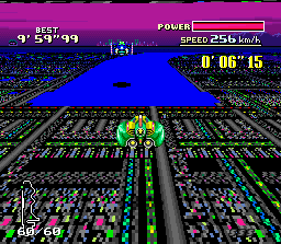
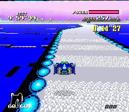
Note how the track specific sets make up most of the non - track tiles, but some common tiles are still used in them.
The compression format for 1 tile consists of 1 byte (the palette byte) and then 32 tile bytes. It is 4bpp compression where the tile bytes in the compressed tile undergoes an OR with the palette byte. The high 4 bits is ORed with the palette byte, then the low 4 bits is ORed with the palette byte. This process repeats 32 times for each tile yeilding a 64 byte tile from 33 bytes. The palette byte always has the upper 4 bits set only as the lower 4 will consist of the tile nybble after the OR. This effectively assigns a set of 16 colours to each tile. As implied, only values 00 - 10...- F0 are valid for the palette byte.
60000 - 61ACF: 208 compressed track tiles. These are shared amongst all tracks.
The below are track specific.
61AD0 - 620FF: Port Town tiles.
62100 - 6272F: Shared with Big Blue and Death Wind.
62730 - 62D5F: Red Canyon tiles.
62D60 - 6338F: Shared with Sand Ocean, Silence and Fire Field.
63390 - 639BF: Mute City tiles.
639C0 - 63FF0: White Land tiles.
Backgrounds
By backgrounds I refer to the 2 scrolling backgrounds that start from the top of the screen and end when the track is rendered. The tilemaps are compressed while the tiles themselves are uncompressed.
One set of 256 tiles is used for both backgrounds of every track.
7E000 - 7FFFF: 256 32 byte / 4bpp tiles.

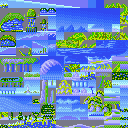
Above are the images of the same tileset with one track specific palette applied to them. One of two palettes can be applied to the tiles. Palette 6 (colors 96 - 111) or palette 7 (colors 112 - 127).
Physics
The physics for each car are quite simple to edit. There's just a few bytes for each category that I currently know of. The order they are stored in is Blue Falcon, Wild Goose, Golden Fox and Fire stingray.
14A4A - 14A95: Acceleration values for the four cars. 10 bytes per car. Consider these the values added to the speed, where the lower entries are added in low speed and the higher entries are added in high speed. You can see the values diminish as you advance through the table. Note that the accessed values are directly proportional to the current speed, and Fire Stingray at 478km / 900h accesses all of them.There are 10 bytes laid out in a similar fashion but I can't find I use for them.
7A91 - 7A98: Top speed. 2 bytes per car. The speed is 'clipped' when the value here is reached.
7A99 - 7AA0: Slipping threshold. 2 bytes per car. This value is initally the same for all cars. It determines the speed when traction is lost and the car starts to slip during turns. The amount of slip is defined below.
7A89 - 7A8C: Slip amount. 1 byte per car. This determines how much the car slips. Higher means greater traction. The Golden Fox has the lowest, the Fire Stingray has the highest.
Here's the shield values too, which define how much is gained / lost in the power bar.
7AB9 - 7ABC: Power loss. 1 byte per car. Higher means more damage is taken.
7AC5 - 7ACC: Power gain. 2 bytes per car. Higher means more power is gained from the PIT thing.